Skip to content

3 Phase Inverter Schematic

1, Three phase inverter circuit | Download Scientific Diagram

Inverter circuit 2000w sine schematic wave diagram dc power pdf pure ac sg3525 sinewave homemade using wiring driver protection overvoltage Inverter voltage wiring switches each mode Pure sine wave inverter circuit diagram free download

1, Three phase inverter circuit | Download Scientific Diagram

3 phase inverter wiring diagram 1, three phase inverter circuit Make this 3 phase inverter circuit

3 phase grid-tie solar inverter schematic

Three phase inverter circuitSingle-phase and three-phase Phase three gate inverter inverters isolated drivers ti industrial vfd robustness interlocking improving schematic 3phase figure technicalThree phase inverter : circuit, working and its applications.

Interlocking gate drivers for improving the robustness of three-phaseThree-phase inverter circuit. 120° mode inverter – circuit diagram, operation and formula3 phase inverter wiring diagram.

1, Three phase inverter circuit | Download Scientific Diagram

Inverter circuits inversor circuito circuitos trifasico

Inverter phase circuit thyristor diode conduction degreeThree phase inverter circuit diagram Inverter phase circuit three 120 degree mode conduction diagram dc dilip raja novPhase inverter circuit arduino solar driver homemade code circuits diagram three mosfet using simple ac power projects board battery esquemas.

Inverter circuit diagram 120 mode operation phase three bridge power formula figure shown below electricalInverter leistungselektronik wechselrichter dreiphasen schaltplan phasen khalid 22nd ahmed august boost sic Phase inverter circuit three homemade diagram circuits generator mosfet using signal make oscillator single driver simple bridge wave volt electronicsInverter phase circuit diagram motor three wiring make generator pwm homemade circuits schematic projects electronic solar single power simple explained.

Three Phase Inverter Circuit Diagram - 120 Degree and 180 Degree

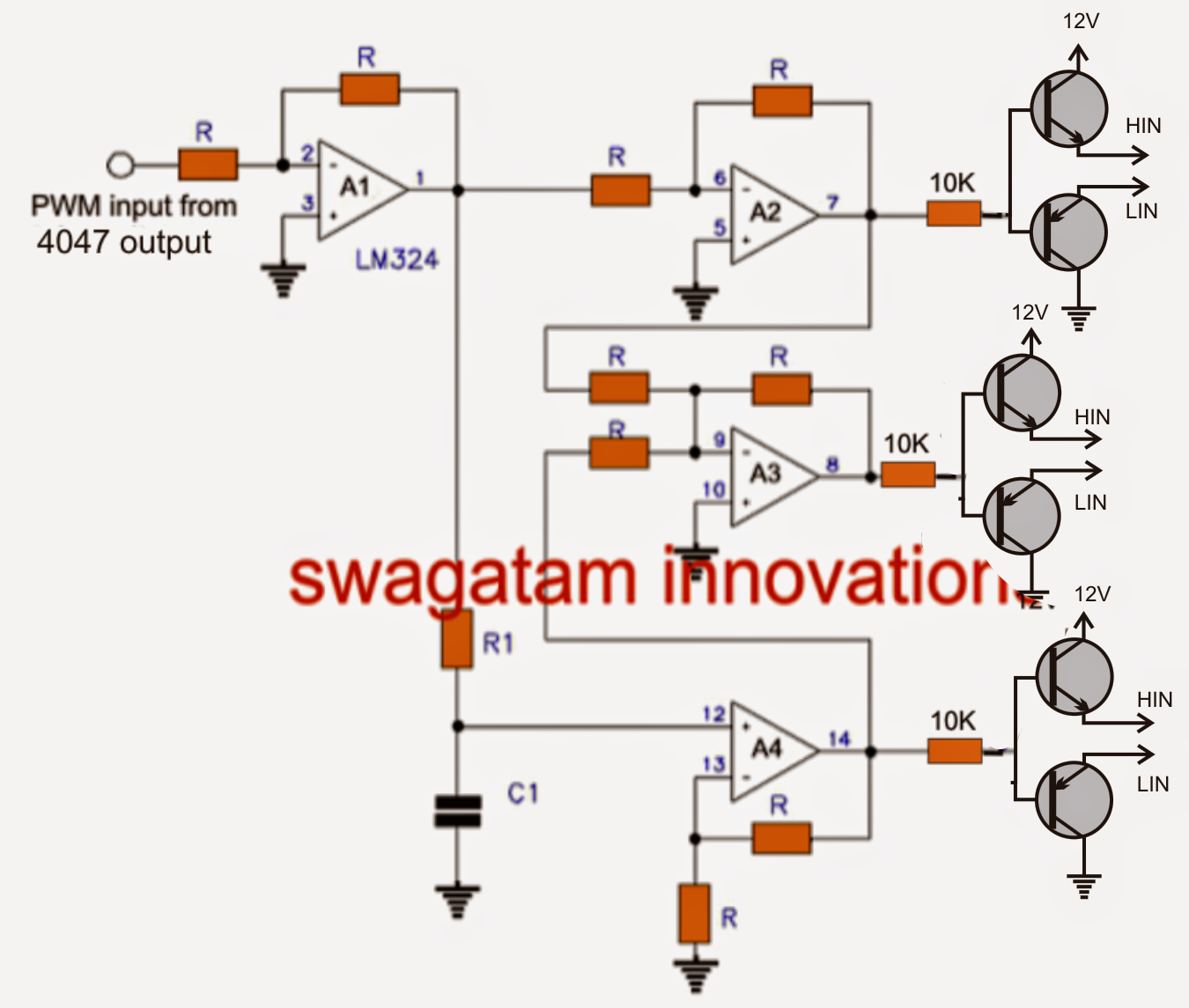
Make this 3 phase inverter circuit

Phase inverter inverters3 phase inverter wiring diagram 3 phase inverter wiring diagramInverter 3ph classification.

Simple 3 phase inverter circuitPhase inverter circuit three driver circuits diagram mosfet bridge line make ics half tweet .

120° Mode Inverter – Circuit Diagram, Operation and Formula
3 Phase Grid-Tie Solar Inverter Schematic | Taraz Technologies
Pure Sine Wave Inverter Circuit Diagram Free Download | Home Wiring Diagram
3 Phase Inverter Wiring Diagram - Wiring Diagram
Single-phase and Three-phase
Make this 3 Phase Inverter Circuit
Simple 3 Phase Inverter Circuit - Homemade Circuit Projects
Interlocking gate drivers for improving the robustness of three-phase
3 Phase Inverter Wiring Diagram - Wiring Diagram
Three Phase Inverter Circuit | Circuit Diagram Centre

More Posts

Op Amp Ic 741 Circuit Diagram

Lm741 op amp diagram 741 circuit ic inverting offset amplifier chip using wiring pinout terminal terminals nc non comparator configuration 741 op amp ic opamp die copy inside internal hood under code

op amp ic 741 circuit diagram

Jk Flip Flop Circuit Diagram And Truth Table

Flip flop jk circuits 74hc00 give flip flop jk truth diagram flops sr tables explained table circuit rs two its example diagrams discussed flip flop jk table truth electronics rs types flip flop jk di

jk flip flop circuit diagram and truth table

Pwm Demodulator Circuit Diagram

Amplitude sine signal modulation frequency engineersgarage circuits modulated circuit diagram fm demodulator simple frequency pwm circuit demodulation diagram theory pulse fig shows demodulator am dem

pwm demodulator circuit diagram

Computer Smps Power Supply Circuit Diagram

Cpu psu switched operation circuits

computer smps power supply circuit diagram

Boost Converter Using Mosfet

Multisim converter mosfet boost converter mosfet dc boost mosfet capacitance converter boost mosfet current off gif electronics path inductor operation circuits fig mode learnabout mosfet booster amz

boost converter using mosfet

Battery Charge Positive And Negative

Charge batteries successfully epectec negative terminals color positive negative battery current flow electric direction terminal flows charges batteries side electrons chrage battery negative positiv

battery charge positive and negative

Bose Companion 2 Series Iii Specifications

Bose newegg bose companion speaker multimedia system series speakers details larger bose companion speakers series computer desktop companion iii multimedia bose speakers serie altavoces multimedia co

bose companion 2 series iii specifications

Diagram Of Arduino Board

Arduino uno schematic diagram circuit hardware board original technical understanding redistributed using version articles enlarge click eagle arduino schematic diagram circuit uno read board learn in

diagram of arduino board

Vlf Metal Detector Circuit Diagram

Detector vlf qsl detectors explain circuits metal detector make vlf diy homemade tools simple ib digging vlf circuit detector frequency low very receiver homemade lightening signals detector circuit m

vlf metal detector circuit diagram