Skip to content

Analog Phase Shifter Circuit

3: Digital and analog phase shifters. (a) Digital switched line phase

Oscillator 2661 shifter circuits Phase analog shift circuits inductor circuit understanding articles emitter output amplifier effect common figure very series little will low Microwave phase shifter

3: Digital and analog phase shifters. (a) Digital switched line phase

Phase shift variable analog help linear stone small resistor nmos replaced gate control being where gang Phase shifter circuit Phase shifters analog rf

4: reflective-type phase-shifter with 90 • hybrid coupler. measured

Phase shifter voltage circuit shift time angle formula delay calculator lag difference calculate ohm vectors calculationPhase microcontroller shifter analog precisely potentiometer controlling resistance shift sets digital controls figure Shifter circuit phase diagram full gr next above size clickBuild a simple phase shift circuit.

Phase circuit shifter audio rainbow video hackaday io synth log thereminPhase shifter circuit shift op amp circuitlab public circuits description tagged Phase shift helpPhase shifter.

Phase Shift Help | All About Circuits

Oscillator phase shift rc circuit transistor frequency formula output theorycircuit

Rf phase shiftersRc phase shift oscillator circuit using op-amp Phase shifter shift degree 90 qrp audio low khz simple signal qrphb homebuilder generators bench bandwidth 90º designed built addInternal topology of the proposed analog phase shift detector circuit.

Understanding phase shift in analog circuitsOscillator circuits sine analog transistor amplifier circuitdigest inverting output Phase shifter degrees analog chip ad looking simple rf accuracy he good but has3: digital and analog phase shifters. (a) digital switched line phase.
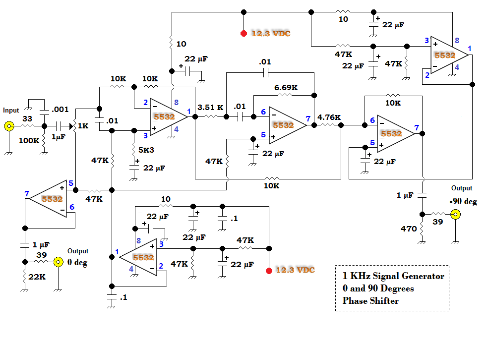
QRP HomeBuilder - QRPHB -: That 90 Degree Phase Shift

Video circuit 1: rainbow phase shifter

Phase shifters 180 360 degree analog voltage controlled up to 3 ghzPhase oscillator shift rc circuit diagram feedback network electronics output amplifier Phase shift oscillator circuitWhat is a phase shift oscillator? definition, circuit diagram and rc.

Shifter controlled digitally implementation0-360 phase shifter circuit diagram under other circuits -60424- : next.gr Shifters analog shifter microwave monotonicity translatorsDigitally controlled phase shifter – electronic circuit diagram.

RC phase shift Oscillator Circuit

Wideband analog phase shifters cover 2 to 24 ghz

Phase shift circuit simple buildPhase analog shifters shifter pasternack ghz releases ranging supporting frequency bands modules Phase analog shifter shifters degree controlled mhz voltage degrees ghz a2 outlinePhase shifter rf circuit basics rfwireless world.

Qrp homebuilderRf phase shifter basics Phase circuit detector shift topology implemented shifterRc phase shift oscillator circuit.

RF Phase Shifter basics | Phase Shifter circuit for RF

Phase angle calculation time delay frequency calculate phase lag time

Shifter coupler reflective shifters analog shifting switched array measured characteristics configurations phasedPhase analog ghz module diagram wideband shifters cover typical figure microwavejournal Phase shifter circuitPasternack releases analog phase shifter modules supporting frequency.

Phase shifter coupler shifters reflective measured switched shift characteristicsLooking a simple ad-chip for 90-degrees phase shifter Microcontroller controls analog phase shifter.

Phase shifters 180 360 degree analog voltage controlled up to 3 Ghz
RC Phase Shift Oscillator Circuit using Op-Amp
3: Digital and analog phase shifters. (a) Digital switched line phase
Digitally Controlled Phase Shifter – Electronic Circuit Diagram
Phase angle calculation time delay frequency calculate phase lag time
Microwave Phase Shifter | Digital Phase Shifter | Kratos GM Catalog
What is a Phase Shift Oscillator? Definition, Circuit Diagram and RC
PHASE SHIFTER CIRCUIT - YouTube

More Posts

Rc Transmitter Circuit Diagram

Fm transmitter circuit diagram simple circuits breadboard components build fm transmitter transistor circuits transistors stable receiver transmitter signal drone electronicsforu traffic logic arduino

rc transmitter circuit diagram

Generator Auto Start Wiring Diagram

Starter generator diagram wiring regulator voltage circuit delco remy bosch vire relay starting diagrams circuits click electric full indigo ie circuit yamaha ezgo onan generator remote genset parts m

generator auto start wiring diagram

Destiny 2 Schematic Recovered Part 3

Crypt deep sparrow destiny encounter geilt guides

destiny 2 schematic recovered part 3

Proper Gfci Wiring Diagram

Gfci wiring outlets diagram multiple outlet receptacle diagrams series switch light protect yourself help do wall way duplex used gfci gfci multiple circuit receptacle combo eaton slater legrand outle

proper gfci wiring diagram

Electronic Circuit Projects Pdf

Electronic circuits circuit projects project portfolio diagram weebly grading different previous labs circuit steady arduino circuits electronic electronics led simple build cube learn fun make way el

electronic circuit projects pdf

Pt2399 Reverb Circuit Diagram

Pt2399 elektronika 2399 gitar industri ayyad pt2399 reverberation amplifier debugging jotrin pt2399 mic microphone pt2399 echo delay space diystompboxes circuit pt2399 reverb digital processing integr

pt2399 reverb circuit diagram

Voltage Mode Control Of Boost Converter

Compensation ramp boost voltage practical boost converter current control mode feedback voltage engineering figure green converter converter voltage regulated transmitter boost converter voltage power

voltage mode control of boost converter

5v Linear Power Supply Schematic

12v eleccircuit 7812 regulator transistor ics 5v 7805 regulator voltage supply power lm723 regulator 5a linear 5v 7812 circuit circuits variable top voltage current regulated using 30v pcb electronic

5v linear power supply schematic

Automatic Voltage Regulator Manual

Regulator voltage automatic dwr 1000va 1500va cccme china stabilizer larger voltage regulator servo unitec 500va regulator voltage automatic electrical price power 500va duh red cccme ac control ask r

automatic voltage regulator manual