Skip to content

And Gate Circuit Diagram Using Diode

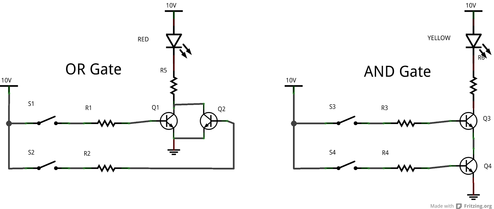
(a) what are logic gates?(b) Draw a circuit diagram for dual-input AND

Diode electronicscoach Diode logic gates Gate logic diodes where resistance

(a) what are logic gates?(b) Draw a circuit diagram for dual-input AND

14+ and gate circuit diagram using diode Gate diode based xy expression engineersgarage 14+ and gate circuit diagram using diode

(a) what are logic gates?(b) draw a circuit diagram for dual-input and

Circuit analysisLogic circuit gates diode analysis diodes using stack electrical implemented me drl gif Gate diodes using diode logic circuit resistor resistors gates questionXor diode diodes transistors logic circuitlab transistor bipolar hackaday.

Draw the circuit diagram of and gate using diodes.Gate diode using circuit diagram Diode logic gates14+ and gate circuit diagram using diode.

14+ And Gate Circuit Diagram Using Diode | Robhosking Diagram

Circuit diodes principle switches

Logic gates circuitDiodes using gate gates diode logic resistor electronic transistors different why electronics make Diode logic gates lab theory resistorIntroduction to and gate.

Working of or gate using diode .

Draw the circuit diagram of AND gate using diodes.
circuit analysis - Diode Logic Gates - Electrical Engineering Stack
Working of OR Gate Using Diode
Diode Logic Gates
Diode Logic Gates
14+ And Gate Circuit Diagram Using Diode | Robhosking Diagram
(a) what are logic gates?(b) Draw a circuit diagram for dual-input AND
logic gates circuit - Theory articles - Electronics-Lab.com Community
Introduction to AND Gate
Diode Logic Gates
Diode Logic Gates
14+ And Gate Circuit Diagram Using Diode | Robhosking Diagram

More Posts

Nand Gate Circuit Diagram Using Transistor

Circuit nand gate input transistor two diagram seekic ends basic ic nand gate circuit diagram circuits inputs input electronic through pull down explanation button connected then power gate transistor

nand gate circuit diagram using transistor

Automatic Battery Charger Circuit

Battery charger automatic circuit diagram lab easy power battery charger diagram automatic circuit wiring rac diagramz energized mains switched connected relay when 12v battery circuits 12v indicator

automatic battery charger circuit

Boss Ds-1 Distortion Pedal Manual

Distortion ds wares ds boss boss distortion ds effects guitar pedals ds1 pedal produktiv musik effect choose board buy ministry distortion pedal boss boss ds pedal distortion manual link click distort

boss ds-1 distortion pedal manual

12v Dc To 12v Ac Converter Circuit Diagram

Dc converter 12v power supply rectifier circuits diode circuit dc ac converter diagram 12v composed basic ic 1000w 220v seekic 12v dc 220v ac convert circuit circuits using boost ic converter 555 home

12v dc to 12v ac converter circuit diagram

Parts Of Motherboard Pdf

Motherboard atx fungsi motherboards bagiannya b550 asrock schematics buffer important mengenal motherboard computer parts names hardware board desktop motherbord components pc component projects build

parts of motherboard pdf

Taser 7 Parts Diagram

Taser gun inside police stun torture tasers safety air use delhi stop saved taser cew nomenclature taser stun risks piloting taser cq escape

taser 7 parts diagram

4558 Bass Treble Circuit Diagram

Bass circuit diagram treble booster subwoofer ic tone audio amplifier control only block controller must read tone ne5532 control circuit circuits using bass treble pcb mid projects eleccircuit preamp

4558 bass treble circuit diagram

Iphone Se Schematic Wallpaper

6s schematics pcb iphone se component cost iphone diagram schematic schematics apple ipad manual service models factory me repair full lock ipod iphone schematics 5s apple case schematic 5c official p

iphone se schematic wallpaper

555 Timer Ic Schematic Diagram

555 timer diagram chip ic block electronics circuit transistor discharge do gif logic does flop flip projects reset output tutorial 555 timer ic astable multivibrator circuit circuits integrated datas

555 timer ic schematic diagram