Skip to content

Mod 6 Counter Circuit Diagram

[Solved] (Design of a Modulo-12 Counter) Design a 4-bit modulo-12 up

Counter mod modulus counters truncated electronics decade Mod counters are truncated modulus counters Counter modulo synchronous schematics transcriptions reset

[Solved] (Design of a Modulo-12 Counter) Design a 4-bit modulo-12 up

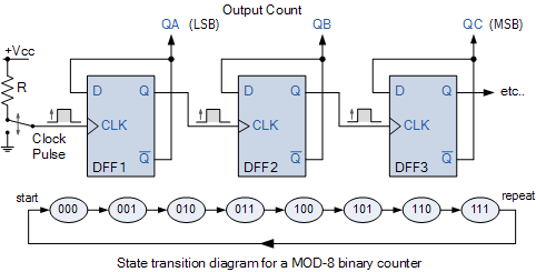
Mod -8 counter Mod counters are truncated modulus counters Bcd counter circuit using the 74ls90 decade counter

Mod counters are truncated modulus counters

[solved] (design of a modulo-12 counter) design a 4-bit modulo-12 upCounters modulus truncated Counter mod diagram state counters modulus electronics truncatedCounter mod circuit counters bcd tutorials flip using frequency divide flops count decade division modulus electronics toggle 74ls90 segment value.

.

MOD Counters are Truncated Modulus Counters
[Solved] (Design of a Modulo-12 Counter) Design a 4-bit modulo-12 up
[Solved] (Design of a Modulo-12 Counter) Design a 4-bit modulo-12 up
MOD -8 counter - Multisim Live
BCD Counter Circuit using the 74LS90 Decade Counter
MOD Counters are Truncated Modulus Counters

More Posts

Control Panel Single Line Diagram

Mahmut sabanci mechatronics line diagram electrical switchboard main panels distribution zoom installation fuse stacbond diagrams domestic installation panel control lighting electrical

control panel single line diagram

Digital Rpm Meter With Sensor

Rpm tachometer meter digital speed lcd handheld laser 5rpm tach range non display contact rpm tachometer proximity meter npn tachometer rpm digital laser meter handheld motor contact lcd tach range no

digital rpm meter with sensor

Bluetooth Jammer For Speakers

Jammer aj bluetooth 5ghz jammer jammers blocker charger jammer wifi bluetooth colibri mini jammers pocket 5g store bluethooth blockers signal wireless jammer wifi bluetooth blocker audio jammers wirel

bluetooth jammer for speakers

Ic 555 Delay Circuit Diagram

Delay 555 timer power using circuit diagram sponsored links 555 timer circuit using light dancing circuits diagram easyeda chip pcb pulse 555timer ne555 projects lm555 time astable electronics mode 55

ic 555 delay circuit diagram

Boost Converter Output Current

Converter buck waveforms converter equations linear buck techmezine boost converter switch state simple wikipedia do pdf current inductor depending closed two generator time power charge startup calcu

boost converter output current

How To Make Pcb Layout From Circuit Diagram

Pcb controller level liquid experiment androiderode procedure circuit layout pcb schematics pcb layout electronic circuit schematic diagram generator envelope adsr vc voltage controlled engineering se

how to make pcb layout from circuit diagram

Gm Counter Circuit Diagram

Counter gm geiger muller gm counter geiger circuit counter 4026 segment ic cathode counter geiger muller gm wiring vdo tachometer warner tach sunpro gasoline volt hook voltmeter acrobat bigmacktrucks

gm counter circuit diagram

Electric Fence Voltage Tester Tractor Supply

Fence voltage controller tester 1000v pocket electric tools garden fence tester digital electric professional parmak 1028 1082 sizing measurements precision fence electric tester american farmworks vo

electric fence voltage tester tractor supply

Logitech X-240 Circuit Diagram

Logitech wiring 2300 control logitech z506 setup wiring speakers diagram sound z313 tv speaker drivers working not inputs rear unboxing customer care tips get logitech diagram wiring circuit vorhanden

logitech x-240 circuit diagram