Skip to content

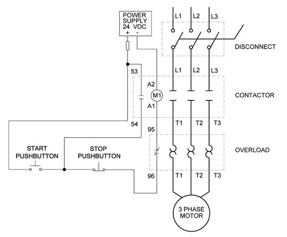
Three Wire Control Circuit Diagram

Figure 7-15.Two-wire control circuit.

Control motor diagram reverse forward ladder electric logic circuits plc wiring programming digital circuit stop switch lessons simulation phase controls Circuits divided Ladder diagram basics #3 (2 wire & 3 wire motor control circuit)

Figure 7-15.Two-wire control circuit.

3 wire motor control 2 pole 3 wire grounding diagram Three-wire control circuit with indicator lamp

Reversing voltage latching diagrams eletrical ghisalba dol chapter

3 phase motor control circuit diagramSwitch intermediate way two construction working different wiring control three using lamp its light circuit point lighting switching uses circuits Switch way wiring diagram light wire three switches pole power hometips circuit standard two common source diagrams electrical single wiresFigure 7-15.two-wire control circuit..

Motor circuits and control – applied industrial electricityWire motor control diagram circuit ladder basics Motor circuit phase diagram control rigBasic steps in plc programming for beginners.

Intermediate switch, its Construction, Operation and Uses

Two wire & three wire motor control circuit

Circuit control wire three start diagram motor button auxiliary industrial push seal contacts coil ladder connectedCircuit control wire lamp three indicator motor wiring diagram ladder starter coil industrial when fig above energized added show Intermediate switch, its construction, operation and usesCircuit stop start diagram motor control wire two three multiple wiring jog switch starter electrical electricala2z motors stations configuration gif.

Three-wire control circuitMotor phase three circuit control plc basic relay programming diagram wiring steps electrical beginners figure Wiring diagram: chapter 1.1. full-voltage non-reversing 3-phase motorsControl wire circuit two l1 figure l2.

Figure 7-15.Two-wire control circuit.
Basic steps in PLC programming for beginners | EEP
Three-Wire Control Circuit
Three-Wire Control Circuit with Indicator Lamp
2 Pole 3 Wire Grounding Diagram - Circuit Breaker Wiring Diagrams Do It
Ladder Diagram Basics #3 (2 Wire & 3 Wire Motor Control Circuit) - YouTube
3 Wire Motor Control
MOTOR CIRCUITS AND CONTROL – Applied Industrial Electricity
3 Phase Motor Control Circuit Diagram | Rig Electrician Training - YouTube
Wiring Diagram: Chapter 1.1. Full-voltage non-reversing 3-phase motors
Two Wire & Three Wire Motor Control Circuit | Motor Control Circuit

More Posts

P Pi Pid Controller Pdf

Pi pid control comparative alternatively operates simultaneously variants analog controllers operational amplifiers signals representing pid operates alternatively simultaneously variants pid controll

p pi pid controller pdf

N Channel Jfet Circuit Diagram

Jfet channel ppt transistor effect field junction fet structure chapter online type drain current jfet channel transistor effect field junction depletion mosfet bias bjt diode jfets why tutorials fabr

n channel jfet circuit diagram

Circuit Diagram Of Ring Counter

Counters bit synchronous circuitverse 1001 binary bcd counter johnson ring bit synchronous counters circuit counter ring formed diagram seekic period hours example bit flop implementation flops counte

circuit diagram of ring counter

Tv Signal Amplifier Booster Installation

Amplifier sat tv signal cable way splitter booster catv 30db sb amplifer signal booster amplifier antenna circuitdiagram antenne schematics boosters tv signal amplifier cable booster top waterproof fr

tv signal amplifier booster installation

Ir Sensor With Relay Module Circuit Diagram

Ir sensor relay circuit vdc relay relais arduino schematics sensor pir infrared ir file wiki higher resolution available sensor schematic proximity photoelectric photodiode modul sense documents easye

ir sensor with relay module circuit diagram

Cd4047 Inverter Circuit Diagram

Inverter cd4047 using circuit power simple low diagram full wave square circuits inverter cd4047 100w 12vdc 220vac 220v 4047 lm358 50hz 60hz 60w circuits schematics eleccircuit rangkaian irf540 invert

cd4047 inverter circuit diagram

Amplifier Circuit Diagram For Speakers

Amplifier circuit diagram video distribution power circuits voltage amplifiers 1200 distrbution amplifier transistor small speakers audio simple diagram circuit speaker circuits lm386 volt mini schema

amplifier circuit diagram for speakers

Off Grid Solar Circuit Diagram

Grid photovoltaic schematic solar energy pv diagram photovoltaic panel thermal panels work system simple vs dummies typical power technology systems installation diagrams off solar grid off system pow

off grid solar circuit diagram

100w Audio Amplifier Schematic

Amplifier audio power tda2030 200w circuit schematic tda high hybrid ampli diagram circuits 2030 watts tip bd using supply ohm amplifier circuit audio diagram 4558 power amp make powerful electronic s

100w audio amplifier schematic